
Why Split-Face and Concrete Blocks are Prone to Water Leaks
Exterior Wall
Why Do the Blocks Leak?
Single-split face blocks and concrete blocks (AKA: CMU for concrete masonry unit) are highly porous. In comparison, being more porous than brick, limestone, granite, and other building exterior wall materials. At a close glance, one can notice the spongy appearance of the block. The small surface voids create avenues for moisture to penetrate by capillary pressure (see photos 1 and 2) and migrate into the material.
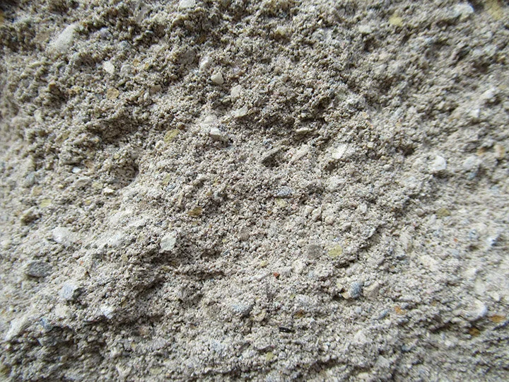
Photo 1: Closeup view of split-face block
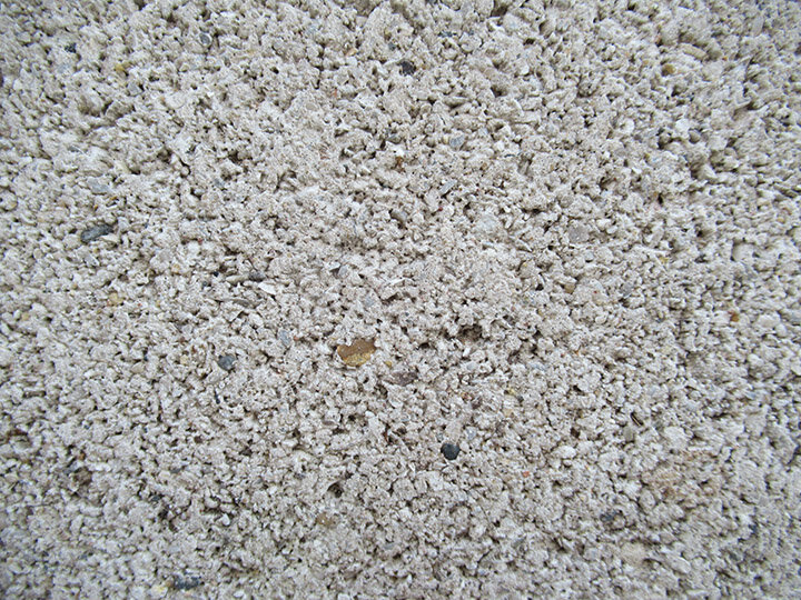
Photo 2: Close-up view of concrete block
The typical mixture contains powdered Portland cement, gravel, sand, and water. The lightweight blocks are created by substituting the gravel and sand with clay, shale, or slate. The most common blocks are the hollow, concrete units that contain voids (or cores) in the interior of the block which help reduce weight and aid installation. On average, the cores are greater than 25% of the gross surface. These cores can be one or a few cell openings based on the construction requirements and manufacturer specifications. As mentioned above, the hollow-core blocks are lighter to handle, easier to install, and are the majority used in exterior construction.
There are several reasons as to the degree of porosity of a block, they are as follows:
Manufacturer’s specifications requirements
Fabrication materials available in the region of said manufacturer
Ratio of water to Portland cement (higher water, more permeability)
Compaction ratio at manufacturer’s plants (if not sufficient, the pores are larger)
“Creeping” (i.e. deformation) occurs in concrete masonry walls after bearing the load of the wall assembly. Creep is the deformation of concrete constructions under sustained load.
A block typically cures for 16-24 hours at high humidity and at an average temperature of approximately 100 degrees Fahrenheit in the manufacturing process. Shortly after the manufacture’s completion, most blocks are delivered to the jobsite and assembled to create walls while the curing is still in progress. The average curing period for concrete is between 21 to 28 days. This makes the block susceptible to developing hairline cracks (i.e. creeping cracks), which can lead to water leakage through the void’s units during rainstorms.
Four Causes of Water Leaks on Split-Face Block Buildings
Leaks at the Flashing
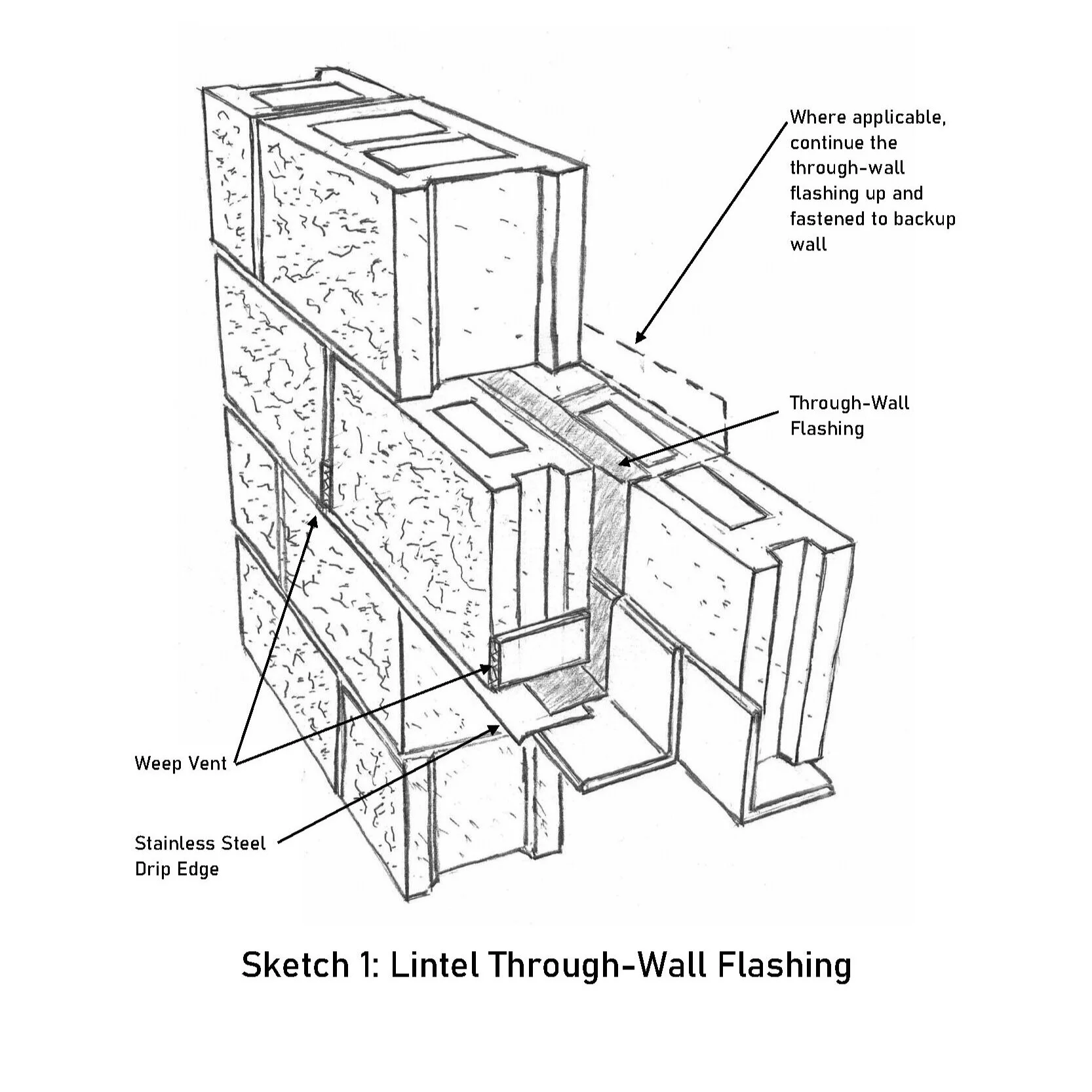
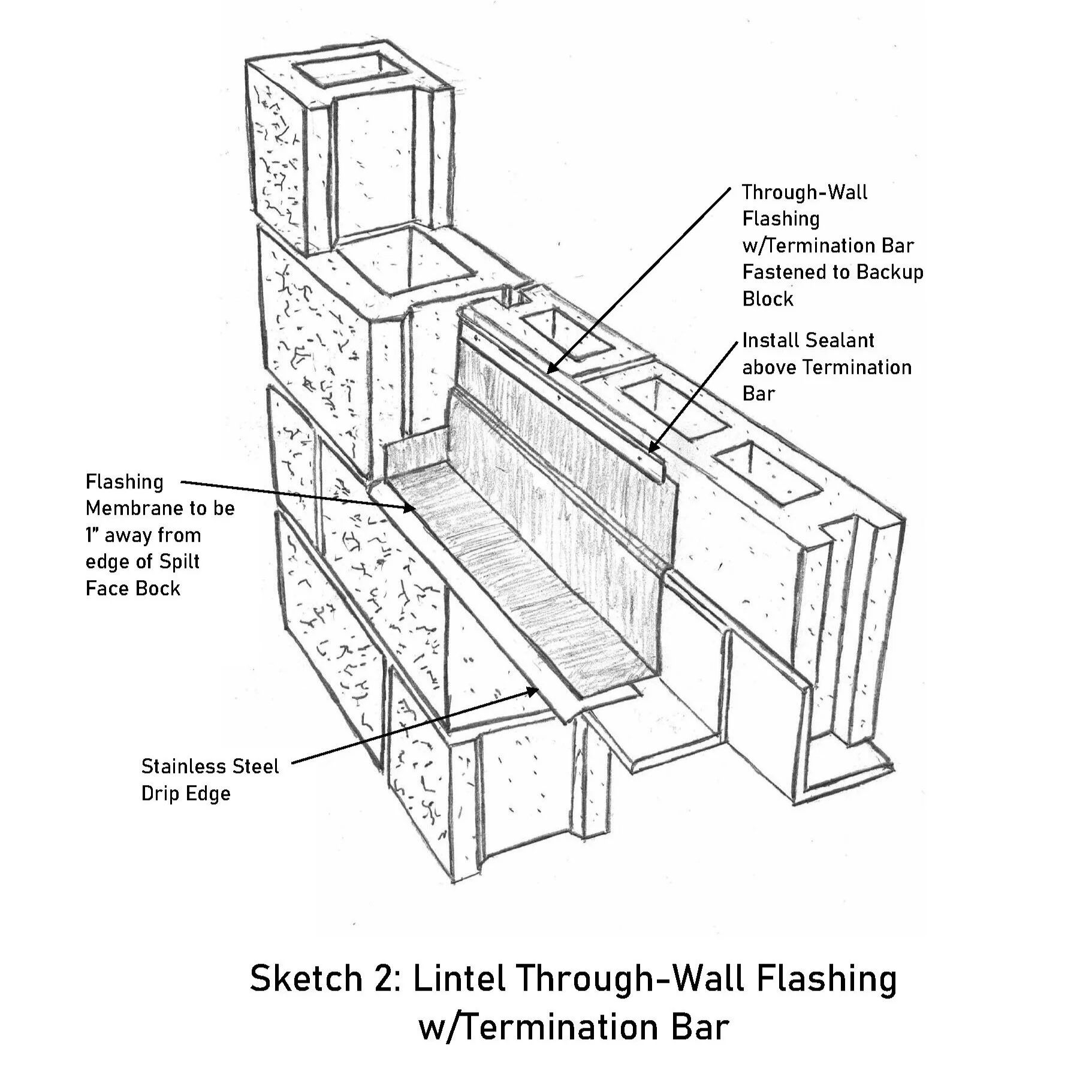
In addition to the block’s composition, there are flashing considerations that might be lacking in the construction of a building. Typically, metal, a composite membrane, and rubber are the three types of materials used for creating an impermeable water barrier and drainage system throughout masonry walls. Above lintels, a composite or rubber membrane is installed above and along the steel angle and rises 4 to 6 inches above the upper edge of the steel angle. The top interior of the membrane should fold back into the backup course joint and turned in (see sketch 1, Lintel Through-Wall Flashing) or a termination bar is to be installed to the flashing and fastened (see sketch 2, Lintel Through-Wall Flashing w/Termination Bar) to backup wall. The flashing on lintel’s ends should be terminated with end-dams (see sketch 3, End-Dam Detail). End-dams should be installed before flashing. Stainless steel flashing sheets are installed under the membrane and extended ¼ inch beyond the wall and turned bent down at 45 degrees to form a drip. This design forces rainstorm water away from the façade and prevents water from penetrating the masonry below. Above this horizontal flashing plane, there should be weep openings installed on the vertical mortar joints above the drip every 16 inches or 24 inches. The most common type of weeping systems are rope, louvered vents, plastic tubes, cellular vents, and masonry weep-holes. Weep openings are drainage avenues in the face of the masonry veneer walls and are installed to facilitate exiting water that has penetrated the interiors of masonry walls.

2. Damaged Flashing around the Joist
The roof and floor supporting joists that penetrate approximately half the interior of the wall assembly should be properly flashed to drain interior moisture outward.
Typical joists are engineered-wood trusses and installed with metal gusset plates underneath to avoid damaging the block when the loads are applied. This includes the installation of through-wall flashing (see sketch 4, Parapet Detail).

3. Damaged Parapet Flashing
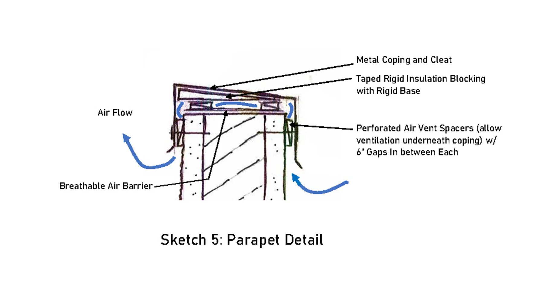
Parapets are exterior walls extending above the roof plane that are commonly capped with concrete, metal, stone, clay tiles, or terra cotta covers. With block masonry, parapets are typically capped with a coping stone, concrete, or metal. Some have flashing between the coping and masonry, and others are without. In both cases the top of parapet walls are sealed from ventilating interior trapped moisture. It’s ideal in the installation of the coping cover to design an avenue of ventilation underneath the covers. This system of ventilating will assist the evaporation of moisture that can get trapped in the masonry’s interiors.
The blocks have interior open cores as mentioned above. By allowing approximately ½-inch of separation between the top of the parapet masonry wall and coping cover, a path will be created for the wall to breathe. That is, the absorbed moisture in the interior wall can evaporate outward through the ½ inch horizontal plane and avoid water penetration into the interior of the building’s spaces (see sketch 5, Parapet Copying Detail). In addition, if the parapet’s masonry coping covers are deteriorated, they should be capped with a metal cover to avoid further damage from weather conditions. Covering the masonry copings with a metal cover might be an alternative to replacing them. The proper selection of metal should be investigated, as some metals, such as aluminum, can corrode when its makes contact with concrete. Additionally, the situation can worsen if the concrete contains calcium chloride as a mixture, or if the aluminum is in contact with a dissimilar metal.
The interior side of the parapet (roofing membrane side) should be investigated to ensure water is not entering behind the cant strip above roof decking. This includes inspecting the exterior side of concrete cement block wall between the coping cover and joists. A cant strip is installed at an angle along bottom corner of parapet wall. The angle shape is to allow the roofing membrane to smoothly curve up from horizontal to vertical, thus avoiding a sharp bend that could potentially damage the membrane. The roofing membrane materials vary from asphalt built-up, modified bitumen, EPDM, and thermoplastic (PVC or TPO) membranes. The metal flashing termination bar should be inspected to ensure that the fasteners have sealant or sealants in good condition. Many times, caulking is missed (or poorly applied) and the opening around the anchor’s penetration holes allow water to leak into masonry.
4. Deteriorated Mortar
The typical mortar used in the construction for split face and concrete block walls is type ‘N’ mortar. The mix is 1-part Portland, 1-part lime, 6 parts of sand, and water. This is the general mix, used in above grade, exterior, and interior load-bearing applications and has a minimum compressive-strength of 750 psi. After 28 days of curing, the strength can increase between 1,500 and 2,400 psi. When the mortar exceeds the compression strength of the concrete block wall, the blocks may begin to develop cracks. More damage is incurred in the winter months with the freezing and thawing due to changing of the temperatures.
Note: Split face and concrete masonry units are specified to meet ASTM C90 by manufacturers, the Standard Specification for Loadbearing Concrete Blocks and should meet the minimum net area compressive strength of 1900 psi.
An attempt to avoid further damage to the masonry units and repointing is necessary by installing a weaker mortar mix into cut out joints, as per ASTM C270. Type ‘O’ mortar mix can be an option. Type ‘O’ mix provides an approximate compression strength of 350 psi and 28-day strength of approximately 1000 to 1500 psi. The mix is 1-part cement, 2-parts lime and 9-parts sand. The idea is to have the weaker be sacrificial and minimize future masonry unit’s damages.

Cracks in the mortar joints of the block wall allow rainstorm water to infiltrate and migrate into the interior of walls and possibly further into the livable spaces. Ideally, the mortar joints when mixed and installed properly should allow the moisture to exit from the interiors of the walls freely. Removing damaged mortar with a grinder to a depth of 3/4 inch to 1 inch is good practice and not less. The removal of mortar from the vertical joints near top and bottom at the intersection of the joints, where round blade of the grinder can damage the block, should be avoided. A flat utility chisel should be used when the blade is nearing an inch of the block. The selection of the proper mortar mix should be considered carefully as mortar sold in today’s hardware stores are structurally too strong for many masonry joint applications. It hardens quickly when fully cured on the walls and mortar’s compressive strength can be greater, than masonry units. The premixed mortar bags contain large quantities of Portland cement which makes it a very hard mix after curing. As mentioned before, in order for moisture to freely evaporate within the joints, the mortar should be softer than surrounding masonry blocks. Mortar that is too hard will force the moisture to escape through the softer blocks and damage it. The block will crack and spall, creating more opportunities for water infiltration. In the winter months, the trapped moisture will freeze in low temperatures and thaw as it becomes warmer during the daylight hours. The cycles of freezing and thawing accelerates the destruction of masonry.
Note: When the hardened mortar is too strong, stresses can be transmitted to the weaker blocks which would then undergo deterioration from cracking and spalling. The harder mortar will have a dissimilar coefficient of thermal expansion to masonry blocks and, as the two materials change their volume differently as temperatures rise and fall, the weaker blocks go through excessive stresses. The blocks can begin to crumble and spall. The cured mortar should demonstrate low shrinkage properties. Careful application of the installation of mortar should be implemented, as the opposite may occur. When weak bonded mortar shrinks, open gaps develop along the perimeter edge of mortar joint’s surfaces which produce avenues for more opportunities for more water to water infiltrate the masonry.
Conclusion
As described earlier, split face block and concrete blocks are highly porous. Most importantly, applying the proper water repellents to the exterior block such as silicones, silanes, siloxanes, or elastomeric coating, can waterproof the block’s facade assembly is the most important. The concrete or cement block wall should be power-washed cleaned (i.e. cleaning the surface from airborne debris) and tested using the RILEM tube to determine amount of volume of water that the wall is allowing to be absorbed. The testing methods are implemented in several locations. This can narrow the selection of best sealer for the particular wall. Next step, contact a sealer (i.e. coating) manufacturer representative and request a site visit to perform a sample test of a two-square foot test of their product on the wall. This will further assist the selection of the most appropriate sealer. Third step, conduct a minimum of three RILEM tests after the water repellent has been applied. Sealer should have been allowed to cure for three days before testing again with RILEM. This will identify how well the sealer performs on resisting water infiltration. Any cracked mortar joints are to be grinded and repointed with the appropriate mortar. Once the sealer has been selected, the product is applied by flood coating the wall and allowing the masonry to absorb the coating into the block.
In addition, follow the recommendations of the American Society for Testing and Materials (ASTM), National Concrete Masonry Association (NCMA), TEK 19-2B, Design for Dry Single-wythe Concrete Masonry Walls, which describes waterproofing approaches for single-wythe exterior concrete masonry facades.
Final note, hiring a professional contractor that is highly experienced with the masonry restoration and repair process of masonry walls will make a world of difference and is money well spent. The initial inspection of the wall condition and developing a report describing the appropriate method for the scope of work is highly beneficial for Owners. The report should not be confused with a contractor’s estimate. The estimate is in addition to the report and can be attached. The report may include photographs and partial drawings sections of the proposed work. As the Owner, you will realize very quickly how qualified the contractor is qualified to perform such repairs. Use a proactive approach by requesting the contractor’s complete exterior wall restoration experience. The report should include a construction schedule to monitor the process of the work. Many Contractors may opt out from preparing such report, but it’s extremely useful throughout the restoration and repair work. This document can be your checklist to determine that the work is progressing as planned and it will save you money in the long run. As the saying goes, pay now or pay later, but you always pay. Paying later is more expensive than paying now.

Photo 3: View of deterioration in progress on concrete block wall.

Photo 4: View of stepped cracking on concrete masonry wall.

Photo 5: View of buildup of efflorescence on a shelf angle line and moisture stains. The wall appears to be absorbing water in large volume during rainstorms.
Note: Masonry material contains a variety of different salts within its makes up (i.e. calcium sulfate, sodium, potassium, calcium carbonate, and a few others). Efflorescence is a crystalline deposit of salts that form when water is present in masonry walls. The white and greyish shades are from salt deposits left behind when water evaporates.

Photo 6: View of hairline cracks throughout the split-face masonry wall.

Photo 7: View of moisture stains on split face wall.
Frank V. Gonzalez, AIA, ALA, GGP is a restoration and preservation architect and founder of US Building Efficiency Solutions, Inc. and US Construction Efficiency Solutions, Inc. He has worked on historical buildings, landmark structures, vintage properties, and contemporary buildings. He has over 30 years in the construction industry and is a licensed architect in Illinois, New York, and Florida. In Illinois he is a licensed General Roofing Contractor, Home Inspector, and in Chicago a licensed General Contractor. He can be reached at frank@us-bes.com.